Understanding of the link between process, microstructure and mechanical properties in AM materials
- Hybrid Additive Manufacturing: UIP in LPBF 316L Stainless Steel
Hybrid additive manufacturing combines layer-by-layer printing with interlayer ultrasonic impact peening (UIP) to enhance mechanical properties of LPBF 316L stainless steel. Microstructural evolution at peened interfaces was mapped using EBSD and hardness testing. A distinct gradient emerges from highly deformed to recrystallized and remelted regions, driven by LPBF’s rapid cooling and steep thermal gradients (Fig. 1). Vickers microhardness peaks at ~330 HV in the UIP layer, dropping to ~180 HV in as-printed zones. Nanoindentation reveals a maximum of 5.1 GPa in the ultrafine deformed region (Zone d, CI = 0.1), with a sharp decline to 3.4 GPa in remelted layers (Fig. 2a). Five zones are identified via EBSD (Fig. 2b): large columnar grains (Zones a, e; CI = 0.9), intermediate columnar (Zone b), fine equiaxed near melt pools (Zone c; CI = 0.8), and ultrafine poorly indexed (Zone d). Partial recrystallization occurs only in Zone c due to limited thermal exposure. Zone e retains elevated hardness from dislocation networks induced by overlying UIP. Recrystallization is suppressed compared to DED hybrids due to high LPBF cooling rates.

Figure 1 – Microhardness profile with EBSD/KAM overlays

Figure 2 – Characterization of transitions zone: (a) Nano-hardness; (b) Five-zone EBSD maps
- Multi-Scale Fracture in LPBF Ni-20wt.%Cr Alloy
Notched bending tests were carried out to investigate the ductile fracture behavior at different scales of a Ni-20wt.%Cr alloy printed by Laser Power Bed Fusion. Three specimens were employed covering a wide range of dimensions, from a few microns to several centimeters. Notched bending tests on LPBF Ni-20wt.%Cr alloy span six orders of magnitude in size, from FIB-milled microcantilevers to macroscopic SENB specimens (Fig. 3). Fracture toughness at initiation drops dramatically from 315 ± 32 kJ/m² (macro) to 0.06 kJ/m² (micro), revealing a strong size effect. Micro-scale crack growth involves severe ductile tearing due to confined plasticity. EBSD at crack tips shows intense lattice rotation in small specimens, with grain boundaries guiding propagation (Fig. 4). KAM maps highlight localized misorientation up to 5° in micro-specimens, versus diffuse deformation in macro-specimens (Fig. 5). The study challenges the applicability of macroscopic standards to micromechanical testing, as plastic zone size violates small-scale yielding assumptions.
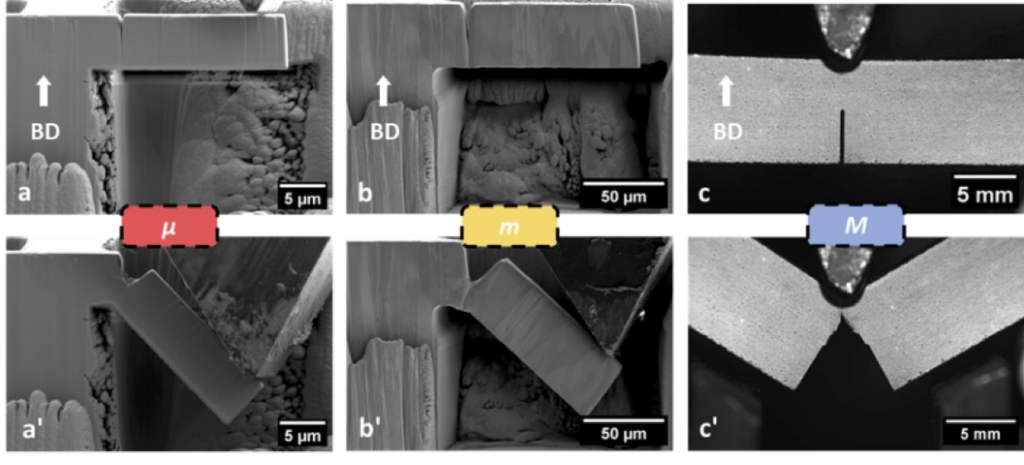
Figure 3 – Illustration of the tested specimens: before and after loading (a,a’) microscopic (small) cantilever prepared with FIB Ga – µ; (b,b’) microscopic (large) cantilever prepared with FIB Xe – m; (c,c’) macroscopic three-point bending – M
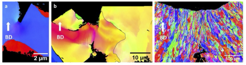
Figure 4 – EBSD images of the crack tip after bending in specimens of (a) µ-specimen, (b) meso-specimen, (c) macro-specimen. The inverted pole figure is drawn to show the microstructure. Grain boundaries (at least 10% misorientation) are shown in black for a and b.

Figure 5 – Kernel Average Misorientation (KAM) map of a (a) µ-specimen, (b) meso-specimen, (c) macro-specimen, after mechanical testing and at maximum crack propagation. The scale goes from 0° of misorientation (blue) to 5° (red)
- Interlayer LSP for Porosity Control in FFF PLA
Fused Filament Fabrication (FFF) as one of the most widely adopted additive manufacturing (AM) technologies globally, due its affordability and minimal waste, suffers from intrinsic porosity resulting from insufficient bonding between extruded filaments. This intralayer porosity negatively impacts fracture performance by weakening the material’s resistance to crack initiation and propagation. To address this limitation, this study investigated the use of laser shock peening (LSP) as a secondary, in situ treatment applied to selected layers during the printing process. Shock waves (>1 GPa) are generated via ND:YAG laser through a water-confined black tape medium (Fig. 6b). Three configurations are compared: as-printed, Hybrid_L1 (LSP every layer), and Hybrid_L3 (every three layers) (Fig. 6a). X-ray CT shows up to 85% localized porosity reduction in peened regions (Fig. 7). Hybrid_L1 achieves near-full densification in treated layers. SENB tests and in-situ imaging reveal increased stiffness and crack path tortuosity in peened samples (Fig. 8), enhancing resistance to crack initiation and propagation.
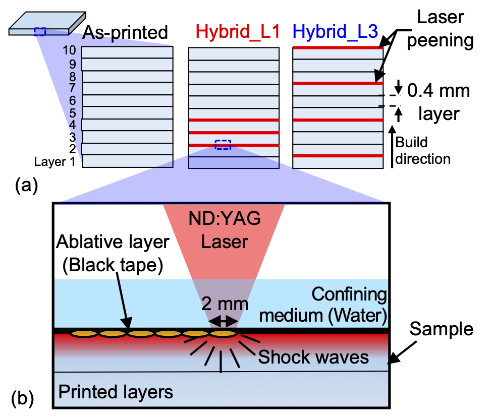
Figure 6 – Schematic illustration of (a) sample configurations (as-printed, Hybrid_L1 and Hybrid_L3) and (b) diagram of the interlayer laser shock peening (LSP) setup
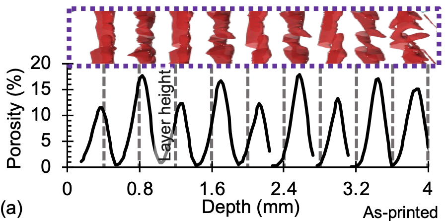
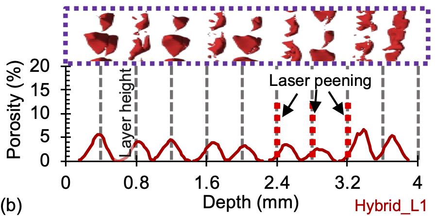
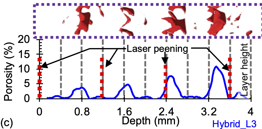
Figure 7 – Depth-wise porosity distribution across the build direction for: (a) As-printed, (b) Hybrid_L1, and (c) Hybrid_L3 samples
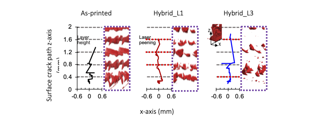
Figure 8 – Surface crack trajectories captured via in situ high-speed imaging for as-printed, Hybrid_L1, and Hybrid_L3 samples
Thermomechanical coupling under fire conditions
In addition to our studies aiming at understanding the link between process, microstructure and mechanical properties, we also have developed experimental characterization means dedicated to the multi-physical analysis of the behavior of mechanically stressed composites under kerosene flame (Fig. 3), adopting a multi-scale approach (micro-meso-macroscopic). Our test bench will eventually enable us to reproduce as closely as possible the critical service conditions (fire in an aircraft engine environment). The multidisciplinary nature of the project (combustion, thermal transfers, mechanics and chemistry of materials) is dealt with through collaborations with the Disordered Systems and Polymers department, the CORIA and LCMT laboratories. Collaborations recently initiated with Safran Nacelles and Daher confirm the relevance of the resources/skills developed and provide the GPM with rare expertise. From this experimental specificity, numerical models are also being developed to predict the thermo-mechanical behavior of organic composites in a wide range of temperatures (up to the thermal decomposition of the matrix and the oxidation of fibers).
- Hydrogen flame resistance of Hybrid CG/PEEK Composites
This work investigates the residual tensile behaviour of hybrid Carbon Glass fibers reinforced thermoplastic PEEK laminates after they were exposed for 5 min to a hydrogen/oxygen flame (Fig. 9). This flame results in a severe thermal aggression characterized by a wall temperature ranging from 900 to 1270°C and with different heat fluxes (from 200 to 800 kW/m²). The thermally-induced damages were examined by means of microscopic observations and micro CT analyses. The results show that the mass loss linearly depends on the measured heat flux for a 5 min exposure. Depending on the fire testing conditions, the mechanical properties in tension (stiffness and strength) are totally degraded after exposure to the highest heat fluxes (600 and 800 kW/m²) but the retention of the tensile properties is moderate (about -35 to -60% decrease in strength and stiffness, respectively) after exposure to a 200 kW/m² heat flux (Fig. 10). The residual tensile properties of CG/PEEK laminates follow master curves representing the correlations between the mass loss and the changes in the tensile properties regardless the heat flux (Fig. 11). These master curves provide a relevant design rule for composite parts to be used under critical service conditions (H2/O2 flame exposure).

Figure 9 – Macroscopic observations of the exposed surface of CG/PEEK laminates subjected to a H2/O2 flame for 5 min at different heat fluxes: (a) 200 kW/m² – (b) 400 kW/m² – (c) 600 kW/m² – (d) 800 kW/m²

Figure 10 – Residual tensile properties as a function of the specimens’ position on CG/PEEK laminates subjected to a H2/O2 flame for 5 min and different heat fluxes: (a) Axial strength – (b) Axial Stiffness
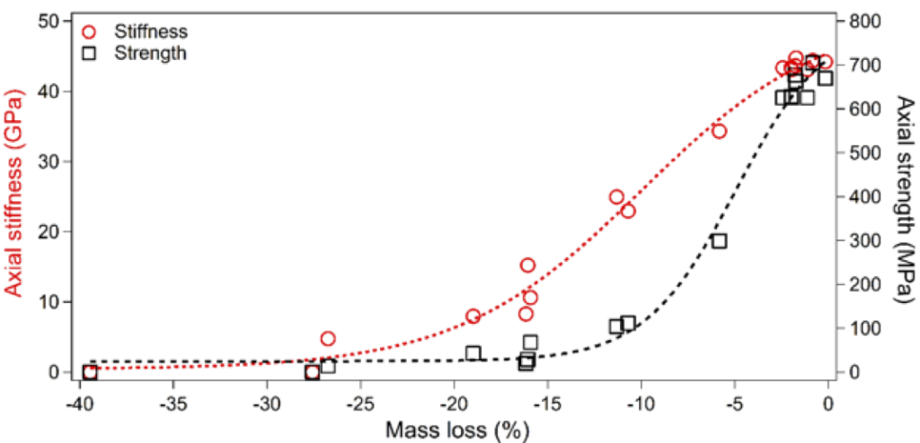
Figure 11 – Master curves (as defined by equations 3) representing the changes in the residual tensile properties as a function of the mass loss of CG/PEEK laminates subjected to a H2/O2 flame for 5 min at different heat fluxes
In-Situ Open-Hole Tension under Kerosene Flame
The objective of this work is to investigate the thermo-mechanical behavior of open-hole hybrid carbon/glass fiber reinforced PolyEther Ether Ketone (CG/PEEK) thermoplastic laminate subjected to the kerosene flame exposure (1100°C and 116 kW/m2 heat flux) in combination with tensile loading (Fig. 12). A specialized flame testing bench has been developed, integrating a tensile mechanical loading and a kerosene burner, to induce in-situ fire-mechanical test conditions. The novel prototype has been employed to monitor the temporal evolution of several physical quantities (temperature and deformation) in the range of fire exposure times up to 900 s, including back surface and through thickness temperature, open-hole deformation and swelling ratio of thickness (Fig. 13). The mechanisms of fire- and mechanically-induced damage are examined through IR camera temperature measurements (Fig.14) and fractographic analyses using tomography and microscopy.

Figure 12 – Design/manufacturing of an intrumented kerosene flame bench

Figure 13 – Full field measurement during combined tensile testing and kerosene flame exposure: (a) Description of DIC measurement range – (b) Axial displacement field measurement

Figure 14 – Full field temperature measurement during combined tensile loading and flame exposure: (a) Back surface – (b) Though-the-thickness
In-Situ X-Ray Tomography of Porosity Evolution
In order to better understand the mechanisms of porosity formation within carbon fiber-reinforced composite laminates, an original in-situ X-ray tomography system with heating cell (25–400°C) enables real-time 3D tracking of porosity formation in carbon fiber-reinforced composites (Fig. 14). This methodology replicates flame-induced thermal loads under controlled conditions. X-ray CT identifies pore types and connectivity evolution. More specifically, it is thus possible to reproduce, under controlled temperature conditions, the effect of the heat produced by a flame during a fire. This tool is proving invaluable for feeding data into a finite element numerical model.
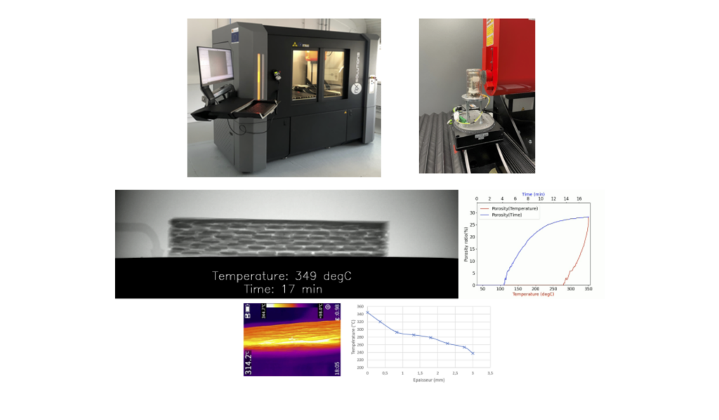
Figure 14 – In-situ X-ray tomography system with heating cell (25–400°C) enables real-time 3D tracking of porosity formation in carbon fiber-reinforced composites
Exposing thermoplastic-based laminates (specifically quasi-isotropic C/PPS) to a kerosene flame creates a highly heterogeneous and rapidly changing temperature field, driven by intense heat, material property contrasts, and polymer phase changes including pyrolysis into gas and char. This is critical for aeronautics in developing lightweight, fire-resistant structural components. Key findings from X-ray tomography include detailed porosity distribution, identifying various pore types and their connectivity. A proposed thermal model accurately predicts through-thickness porosity evolution, both between plies and within individual plies, capturing steep intraply gradients seen experimentally (Fig. 15). Extending to thermomechanical modeling yields results matching experimental stiffness degradation under fire. It also effectively simulates time-dependent load redistribution across plies during fire exposure.

Figure 15 – Evolution of the porosity content through the thickness of the laminates after 60s flame exposure as measured from X-Ray tomography analyses and as estimated from the modeling